Background
The USB standard is complex. With the introduction of USB3.1 and Type-C connectors, it became really complex.
Further, USB ports aren't just used for data transfer anymore, they are also used as a power supply source for a multitude of different peripheral devices. Some of which including phone chargers, fans, LED lights, hubs, docks, toys and many other unusual devices.
In the USB 1.0 specs, a standard downstream port is capable of delivering up to 100mA at 5Volts, over 4 wires. (Two data wires, +5V and ground).
In the USB 2.0 specs, a standard downstream port is capable of delivering up to 500mA at 5Volts, again over over 4 wires. (2.5 Watts) once a device is enumerated. The limit is just 100mA prior to enumeration.
USB 3.0 ports add an additional row of five pins to make a total of nine wires. They are also able to supply more current. There are three kinds of USB port dictated by the 3.0 specs (and another specification known as the Battery Charging Specification, BC1.1 and then BC1.2)
USB Type-C Power Delivery
With the Type-C connector the USB power delivery specification was also introduced, which allows power transfers of up to a massive 100W at varying voltages. The combination of a voltage level and current limit was referred to as a "profile".
Devices negotiate what power they need with the host via a new protocol. Ensuring that a device doesn't draw too much current, which would cause things to fail, catch on fire, melt or explode. The cables themselves also need to be intelligent cables containing a chip to indicate their capacity.
More things to go wrong
With this complexity there are a lot more things to go wrong. Typical faults include.
Testing solution
To fill the need for a testing solution we have spent the last 6 months working on a USB power delivery testing device. Features include,
Status
At the moment it is at the final prototype stage and we are about to go into mass production.
The USB standard is complex. With the introduction of USB3.1 and Type-C connectors, it became really complex.
Further, USB ports aren't just used for data transfer anymore, they are also used as a power supply source for a multitude of different peripheral devices. Some of which including phone chargers, fans, LED lights, hubs, docks, toys and many other unusual devices.
In the USB 1.0 specs, a standard downstream port is capable of delivering up to 100mA at 5Volts, over 4 wires. (Two data wires, +5V and ground).
In the USB 2.0 specs, a standard downstream port is capable of delivering up to 500mA at 5Volts, again over over 4 wires. (2.5 Watts) once a device is enumerated. The limit is just 100mA prior to enumeration.
USB 3.0 ports add an additional row of five pins to make a total of nine wires. They are also able to supply more current. There are three kinds of USB port dictated by the 3.0 specs (and another specification known as the Battery Charging Specification, BC1.1 and then BC1.2)
- A standard downstream port (SDP). Found on most computers, with a current limit of 500mA before enumeration and 900mA after enumeration.
- A charging downstream port (CDP). Found on some computers, 1500mA (1.5A, 7.5W)
- A dedicated charging port (DCP) for "dumb" wall chargers, also allowing 1500mA (1.5A, 7.5W)
USB Type-C Power Delivery
With the Type-C connector the USB power delivery specification was also introduced, which allows power transfers of up to a massive 100W at varying voltages. The combination of a voltage level and current limit was referred to as a "profile".
- Profile 1 (Default): 10 W (5 V @ 2 A)
- Profile 2: 18 W (5 V @ 2 A -> 12 V @ 1.5A)
- Profile 3: 36 W (5V @ 2 A -> 12 V @ 3A)
- Profile 4 (Micro B/AB limit): 60 W (5 V @ 2 A -> 20 V @ 3 A)
- Profile 5 (Standard B/AB limit): 100 W (5 V @ 2 A -> 20 V @ 5 A)
Devices negotiate what power they need with the host via a new protocol. Ensuring that a device doesn't draw too much current, which would cause things to fail, catch on fire, melt or explode. The cables themselves also need to be intelligent cables containing a chip to indicate their capacity.
More things to go wrong
With this complexity there are a lot more things to go wrong. Typical faults include.
- Vendors overstating the current limit of the host or USB charger
- No overcurrent protection in some devices, increasing the changes of catastrophic failure.
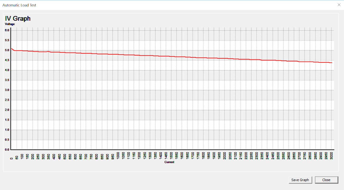
- Large voltage drops at high current levels over inferior cables, especially long cables
- Voltage instability near the maximum current limit
- Voltage instability resulting from sudden changes in current.
- Various type of protocol errors in the power negotiation phase
- Advertising incorrect profiles
- Data corruption on the data lines during high current load on the power lines
- Out of spec voltages
- Too much ripple
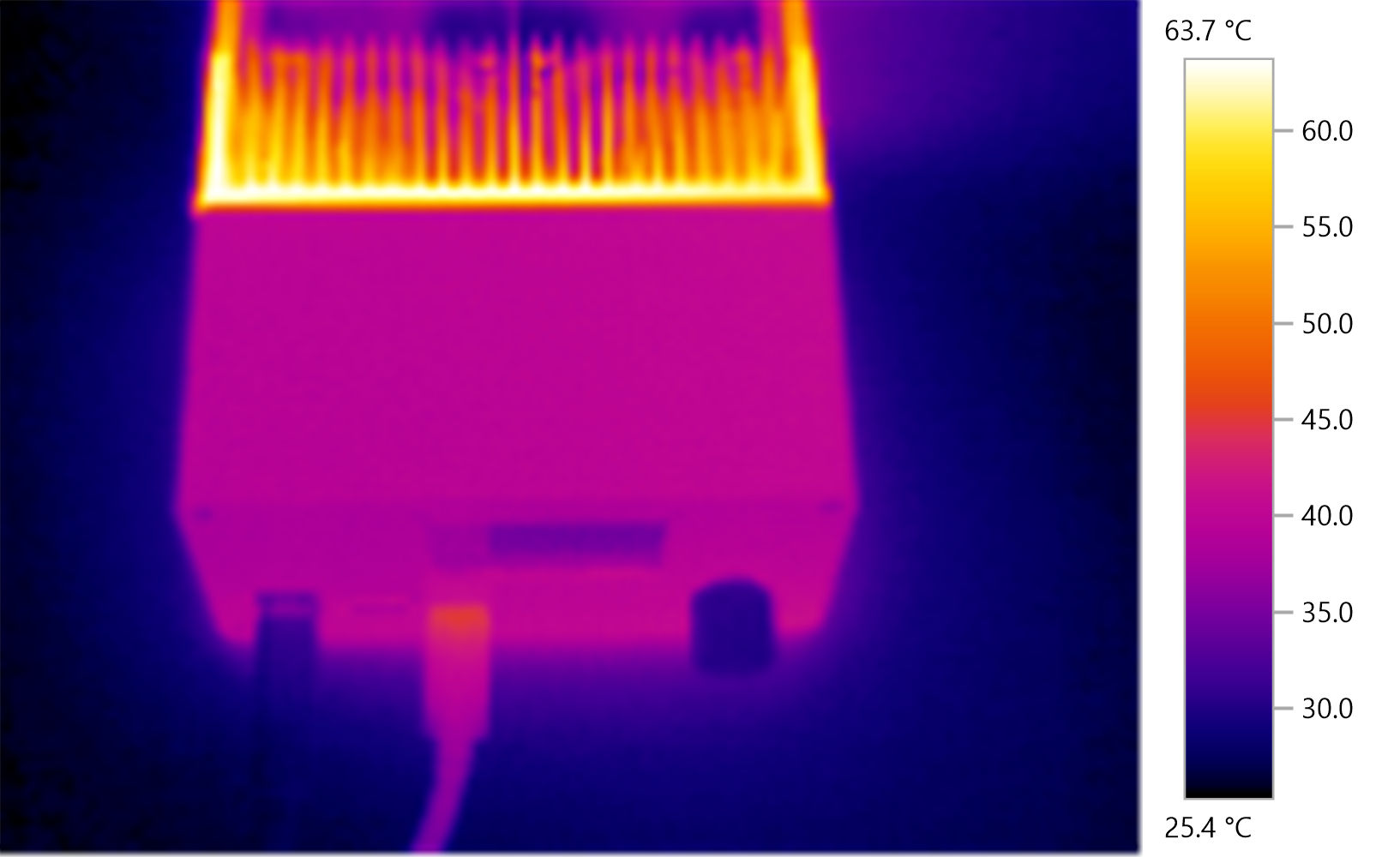
- Overheating when at maximum wattage
Testing solution
To fill the need for a testing solution we have spent the last 6 months working on a USB power delivery testing device. Features include,
- Tests the power delivery capability of USB ports up to 100 Watts according to USB Battery Charging 1.2 and USB Power Delivery standards.
- Detects proprietary chargers and adjusts the maximum current accordingly
- Negotiates voltage levels with host PD controller chip to switch between different voltage levels from 5V to 20Volts.
- Dissipates 50 watts of continuous load, and up to 100 watts for short periods (via dual fans & a large heatsink).
- When used in conjunction with the USB loopback tester, tests communication speed, data integrity, and power delivery of USB ports simultaneously.
- Current can be adjusted with milliamp precision using rotary dial or via PC software application.
- Controllable and configurable over USB interface via an API to adjust the load.
- Built-in protection against overcurrent, over voltage, over temperature and ESD.
- Isolated USB Monitoring port which protects the monitoring machine.
- Bootloader which allows updating the firmware in field.
Status
At the moment it is at the final prototype stage and we are about to go into mass production.


Comment